Behavior Diagram
also known as: Behavioral Diagram, Dynamic View, Activity Diagram, Use Case Diagram, State Machine Diagram, …?
Classification
- #method
- #roles/designer
- #used-by/designer #used-by/engineers
- #medium/diagram
- #tools/digital #tools/non-digital
Intent
- Describe the behavior of game objects and their interaction with each other in general scenarios and specific use cases.
- Establish a unified modeling language (UML) understood by the team.
Problem
General
- Game objects exhibit various behaviors. They can also be independent from the player, with time-based actions, repetitions, player-invoked actions, and unique actions.
- It’s necessary to describe these actions, their impact on the surrounding environment, and their effects on the objects themselves.
- It’s crucial to understand how different scenarios can alter the behavior of objects.
Specific
- Take a level in a stealth game for example, how can you guide the player through it effectively?
- What actions can the player take, and what are the specific consequences of these actions? Will a guard be alerted if the player steps into the light? How will the guard react? Does the game end immediately, or does the player have a chance to prevent the guard from alerting others? Does combat become necessary?
Solution Approach
General
- A behavior diagram is used in UML (Unified Modeling Language), a model langage used to communicate designs to a vast range of people who know the language. It’s intuitive and easy to understand.
- A behavior diagram is a mix of:
- A Use Case diagram: Depicting interactions between users and the system. Bubbles/Elipses show the actions by the different actors within the system. The actors and the actions are connected through lines. (Source: Unified Modeling Language)
- An Activity Diagram: Representing processes and activities within the system. Is not bound to a single Use Case but instead depicts the system as a whole. Models a system with its actions step-by-step (Source: link)
- A State Machine Diagram: (also known as State Diagram, Statechart) Depicts the system in various states that can be entered and left by the system. Compared to the other two diagrams, it describes what a system IS rather than what it DOES. (Source: Unified Modeling Language)
- Difference of Behavior Diagrams and Structural Diagrams:
- Structural Diagrams emphasize on the objects and attributes within a system, focus on the static nature of objects (what it IS, not how it REACTS), including class diagrams and composite structure diagrams
- Behavioral Diagrams highlight the dynamic behavior between objects, emphasize change and how a system can evolve and change over time, shows how objects work together (Source: link)
- You can use any type of the above-mentioned behavior diagrams or mix them to find the best depiction of your system for your scenario
Specific
- To abstractly define how a player can interact with a level, create a behavior diagram.
- Begin by defining the player as an actor and NPCs as other actors, specifying the player’s actions and how NPCs respond.
- Consider using State Diagrams to depict a changing game world based on player decisions. For example, if they have the choice to damage an object, the room they are in becomes damaged from the action. If they decide to persuade a guard and it does not work, the guard can become angry which is also a state that triggers certain actions.
Application
Input
- Definiton of actors, game objects and the setup of the level
Application
- Represent actors as stick figures.
- Illustrate possible actions of actors as ellipses/circles and connect them to affected actors.
- Predict consequences of actions and define them as states or new actions. Determine which actors are affected and how these actions shape the level or world.
- This process helps identify potential outcomes and understanding on how to guide player behavior.
Output
- A behavior Diagram that can be shared with teammates, digital or non-digital
When to use it
- Deciding on gameplay cues, possibilities, storytelling incentives
- Open-world or more story-based? Give the player freedom or guide them?
- Be prepared for unpredictable player behavior
- Reduce bugs und unforeseen outcomes/loopholes
Relevant Roles using this model
Relevancy in the following processes
- Game Development Decision making process?
Applicability
- Fitting for decision-making and planning.
- Addressing complex level designs within limited design languages.
- Analyzing time-based interactions unrelated to spatial decisions.
- Beneficial when involving players and team members in collaborative design and level analysis.
- Consider using it in parallel with reference collection or after drawing a map.
- Can complement Nintendo Power Method and Pacing Diagram, as they describe level progression with story elements, which can align with actions and reactions of game objects on a micro level.
Pros and Cons
Pros:
- Based on UML, a universally accepted modeling language, facilitating team communication.
- Simplifies complex interaction structures into simple geometric forms and concise phrases.
- Reduces the complexity of game development.
- Enhances anticipation when used in conjunction with Pacing Diagrams.
- Complements artistic choices due to its focus on storytelling and interactions.
Cons:
- UML has drawbacks that also apply to Behavior Diagrams in level design (for further insides on this topic, visit link 1, link 2)
- May have unnoticed loopholes that players can exploit; not fail-proof.
- Does not depict spatial relationships; use Drawing a Map for that purpose.
Relation with other Methods
- Nintendo Power Method and Pacing Diagram are good additions
- Reward Schedule can be used in addition to match the rewards the player receives (actions that can also be depicted as circles/ellipses within a behavior diagram)
- Lenses can help understanding the player behavior
Examples
-
Example of a State Diagram in a Serious Game
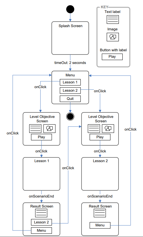 (Source: [[ Towards a Domain Specific Modelling Language for Serious Game Design.pdf ]] )
 -
A Use case diagram for a restaurant
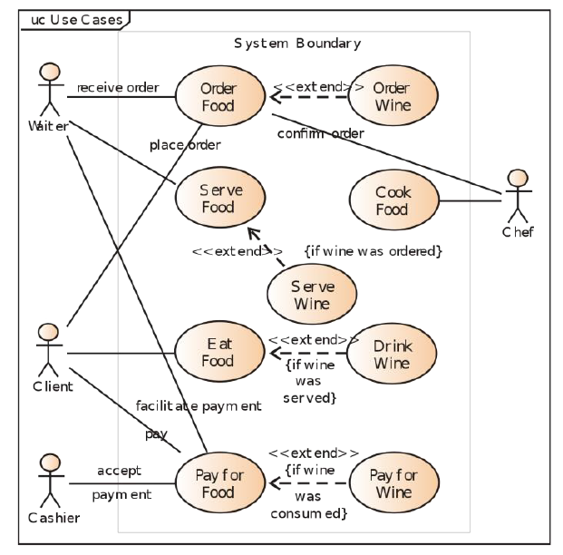 (Source: link)
Relevant Tools
- Model-driven Engineering -> Framework proposed by Stephen Tang et al. in [[ Towards a game-Chatbot Extending the Interaction in Serious Games.pdf ]]
- Digital Diagram Tools
Relevant Literature
A Systematic Review of Game Design Methods and Tools p.10 (25)
Toward a Domain Specific Modeling Language for Serious Game Design
...